Multi-Stream AI
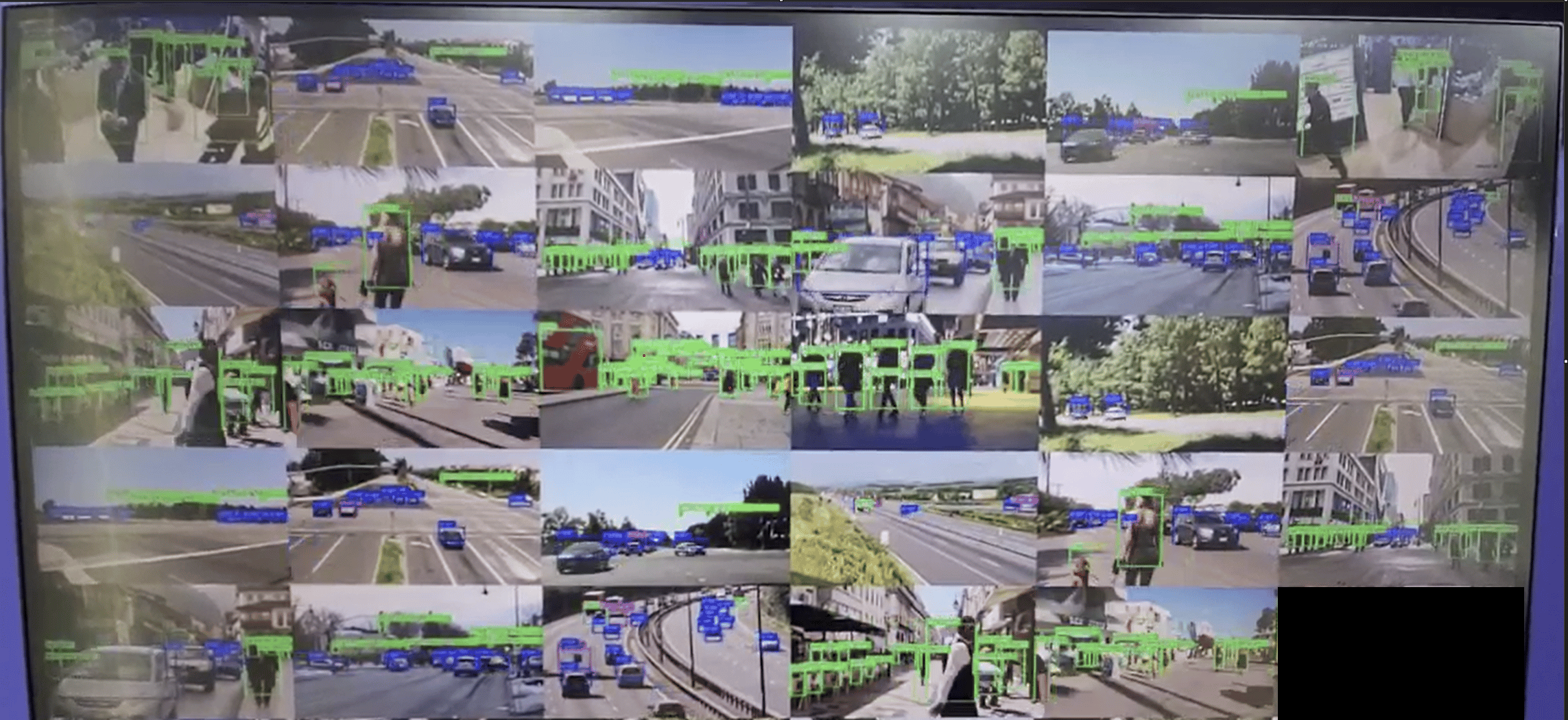
Process up to 31 concurrent IP camera streams in parallel with YOLOv8 object detection, compositing all streams into a unified video wall output and streaming over RTSP or WebRTC.
Introduction
Modern security systems rarely depend on a single camera. In real deployments, operators need to monitor dozens of streams simultaneously across warehouses, campuses, retail spaces, and large environments. As camera counts grow, manual monitoring becomes impractical, and traditional CPU-only processing struggles to keep up — increasing latency, power usage, and system load. The IM SDK addresses this directly. It enables scalable, real-time multi-stream video analytics at the edge using hardware-accelerated GStreamer plugins that shift demanding work — decoding, frame preparation, AI inference, and encoding — entirely onto dedicated hardware blocks. Frame preparation includes resizing frames to match model input, converting YUV to RGB, and normalizing pixel values for neural network input. The pipeline processes each stream independently, running object detection on every input source while preserving a consistent visual experience. To improve efficiency, inference runs at a reduced frame rate without affecting the continuity of the displayed output. Detection results are rendered as RGBA overlay masks and composited with the corresponding video feeds, allowing object visualization without modifying source frames directly. Integration with Qualcomm AI Hub gives developers access to optimized, ready-to-use models such as YOLO-based detectors for multi-stream analytics. The complete application source code is available here.Use Case Overview
Video Input
Each RTSP camera provides an H.264/H.265-encoded stream decoded into raw YUV frames for inference and visualization.
Frame Rate Optimization
videorate controls the inference processing rate to improve performance while preserving temporal accuracy in the displayed output.Object Detection
Each decoded frame is analyzed independently by an object detection model running on the Qualcomm NPU.
Detection Output
The model produces an RGBA overlay mask containing bounding boxes and class labels over a transparent background.
Composition
qtivcomposer composites all stream masks onto their corresponding video frames and tiles them into a configurable M×N grid (up to 8×4).Metadata Synchronization
qtimetamux attaches detection results as structured per-frame metadata synchronized with the video stream.Pipeline diagram
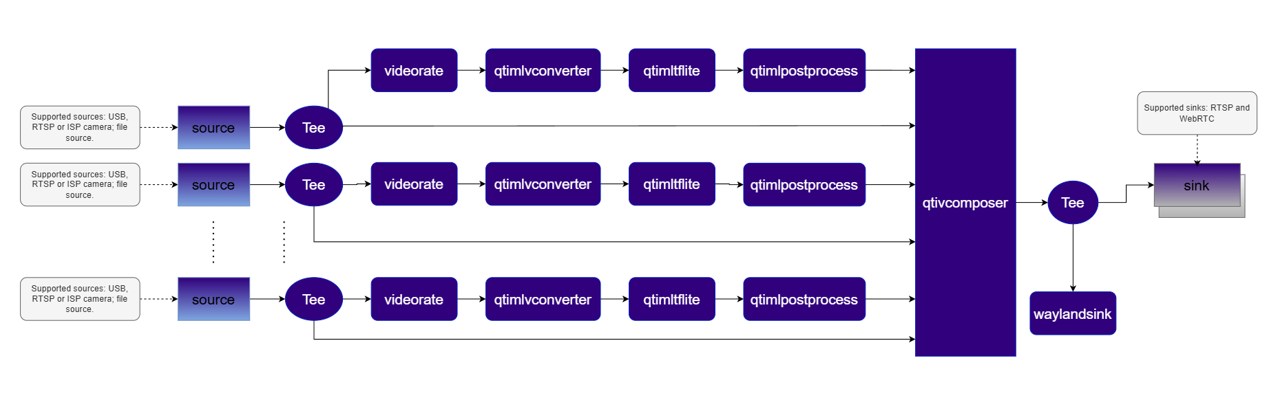
Elements used in pipeline
| Element | Description |
|---|---|
source | Accepts input from an RTSP camera, USB camera, or local file source. |
tee | Splits each decoded stream into parallel branches for simultaneous display and AI inference. |
videorate | Adjusts the video frame rate — reduces rate by half to lower compute load while maintaining display continuity. |
qtimlvconverter | Prepares frames for inference — resizes, converts YUV to RGB, and normalizes input to match model requirements. |
qtimltflite | Runs the TFLite object detection model on each frame using the Qualcomm NPU via the QNN external delegate. |
qtimlpostprocess | Converts raw output tensors into structured bounding boxes and labels via a dynamically loaded module. |
qtimetamux | Synchronizes inference results with the original video stream as per-frame structured metadata. |
qtivcomposer | Composites video from all streams into a single 8×4 grid output and overlays RGBA masks onto corresponding YUV frames. |
v4l2h264enc / h264parse | Encodes the composited stream into H.264 format for transmission. |
waylandsink | Displays the composited video locally on the device. |
sink | Streams the encoded video and metadata over RTSP or WebRTC via rtspbin or webrtcbin. |
How it works
Stream Ingestion
Each
rtspsrc element receives an RTSP stream. The RTP/H.264 payload is depayloaded, parsed, and decoded into raw NV12 frames by the hardware decoder.Parallel Processing
A
tee splits each decoded stream into two branches: one forwards frames directly to the compositor, the other runs AI inference at a reduced frame rate.ML Inference
The inference branch runs through
qtimlvconverter → qtimltflite → qtimlpostprocess producing an RGBA overlay mask.Composition
qtivcomposer tiles all annotated streams into an 8×4 grid. If detection runs at a lower rate than the input, the most recent mask is reused to maintain a stable overlay.Run application on device
Setup Requirements
Hardware
| Component | Description |
|---|---|
| Edge Device | IQ9 — Primary processing unit for AI inference and video composition. |
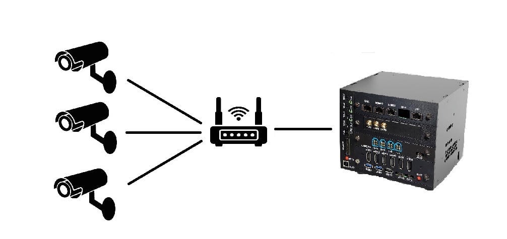
| Camera Source | IP/RTSP cameras. A local file source may be substituted if no physical camera is available. |
| HDMI Display Monitor | Connected to the edge device for rendering and visualizing pipeline output. |
| PoE Switch | Powers IP/RTSP cameras and provides network connectivity over a single Ethernet cable per camera. (Required for IP/RTSP setups only.) |
| Local Network | Ensures the edge device, cameras, and host machine are reachable on the same network. (Required for RTSP input or RTSP/WebRTC output.) |
Software
Flash your Qualcomm Edge device by following the device setup and flashing instructions here. Once your device is ready, follow the instructions below to set up the Security Video Wall pipeline.AI Model and config files
| File | Download | Save as |
|---|---|---|
| YOLOv8 W8A8 model | Qualcomm AI Hub — YOLOv8 Detection | yolov8_det_quantized.tflite |
| Detection labels | yolov8.json | yolov8.json |
| Sample video | Input video | video.mp4 |
Note: A display must be connected to the device. If no display is available, use the --no-display flag.
RTSP output
RTSP output
WebRTC output
WebRTC output
Display only
Display only
Note: This example uses an offline video file as input. To use IP/RTSP cameras, updateIt produces an AI-annotated video stream. To visualize the results, refer to the Host-Side Visualization section below.--input-type=rtspand--input-config=rtsp://...accordingly.
Visualize the Results - Host-Side Visualization (Windows + WSL)
This section describes how to run the visualization client on a Windows host machine using WSL (Windows Subsystem for Linux). The client renders the live composited video stream alongside a real-time AI metadata panel. 📥 The visualization client script can be downloaded here: rtsp_webrtc_client.zip It displays:- Left panel — Live composited video stream with AI overlays from all camera inputs.
- Right panel — Real-time AI metadata (JSON): object detections, bounding boxes, and confidence scores per stream.
RTSP
RTSP
WebRTC
WebRTC
| Panel | Content |
|---|---|
| Left | Real-time composited video — all streams tiled in a grid with bounding boxes and labels |
| Right | Live AI metadata — per-stream object detections, bounding boxes, and confidence scores |
Command-Line Options
--input-count
--input-count
Specifies the total number of input video streams. Must match the number of
--input-type and --input-config entries. Valid range: 1 to 31.--input-type
--input-type
Selects the video input source for each stream.
| Value | Description |
|---|---|
rtsp | External IP/RTSP camera. Requires --input-config=rtsp://.... |
file | Local H.264-encoded video file. Requires --input-config=/path/to/video.mp4. |
--input-config
--input-config
Specifies the input source configuration for the selected
--input-type.| Input Type | Value |
|---|---|
| RTSP | rtsp://<ip-or-url> |
| File | /path/to/video.mp4 |
--output-type
--output-type
Defines how the processed output is delivered.
| Value | Description |
|---|---|
none | No video output (headless mode). |
file | Save encoded output to a file. Requires --output-config. |
rtsp | Stream over RTSP. Requires --output-config=<port>. Access at rtsp://<device-ip>:<port>/live. |
webrtc | Stream over WebRTC. Requires --output-config=ws://.... |
--output-config
--output-config
Specifies the output destination configuration.
| Output Type | Value |
|---|---|
| File | /path/to/output.mp4 |
| RTSP | <port> |
| WebRTC | ws://<signalling-server>:<port> |
--model-base-path
--model-base-path
Root directory for AI model, label, and configuration files.
| Asset Type | Resolved Path |
|---|---|
Model files (*.tflite) | <base-path>/models/<model_file> |
Label/settings files (*.json) | <base-path>/labels/<labels_file> |
--no-display
--no-display
Disables local on-screen rendering. Recommended for headless deployments, remote streaming (RTSP/WebRTC), or performance optimization.
--num-npus
--num-npus
Specifies the video frame rate for the input stream.
--webrtc-id
--webrtc-id
Specifies the local WebRTC signaling client ID.
Implementation Deep-Dive
1. Application Configuration and Runtime Context
1. Application Configuration and Runtime Context
The application separates user configuration from runtime state.
2. Reusable Pipeline Skeleton
2. Reusable Pipeline Skeleton
The pipeline is assembled from three logical sections: input branch, output branch, and application-specific user branch.
3. Multi-Input Configuration and Composer Geometry
3. Multi-Input Configuration and Composer Geometry
Constants define the maximum input count and compositor layout.Each input stream contributes one direct video layer and one RGBA overlay layer to the same grid position in the compositor.
4. WebRTC Signaling
4. WebRTC Signaling
WebRTC signaling uses explicit SDP offer/answer and ICE candidate exchange via WebSocket with
libsoup.| Callback | Responsibility |
|---|---|
on_offer_created | Constructs and sends the SDP offer |
on_ice_candidate | Transmits ICE candidates to the signaling server |
on_ws_message | Handles incoming WebSocket signaling messages |
Build the Application
- Source code: gst-video-wall
- Build instructions: Steps to build custom application